There is a complementarity (spelled with an ‘e’) about observation. The processes of the emanation and detection of radiation are completely symmetric, and in fact, are co-conspirators. The ‘observation’ of light is an irreversible aspect of the ‘detection’ of light. This is shown in the diagram of figure 1 below.
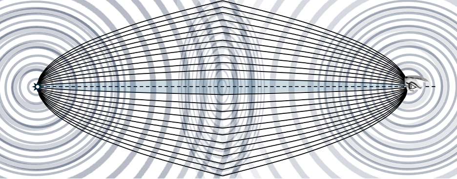
Figure 1: Paradigm of observation of electromagnetic radiation
We have spherical wavefronts of sinusoidal oscillations of electric and magnetic fields, Fresnel zones of areas on a plane throughout which oscillations share the same phase even though displaced in space, and parabolas, between which oscillations proceed in phase. Within a Fresnel zone, notably the central zone, the spherical wavefronts are virtually indistinguishable from planal surfaces. Criteria requires all waves through the zone can be out of phase by no more that one quarter of a wavelength.
Let’s define some of the terms: First of all the sinusoidal oscillations involve sums and differences of sines and cosines, which we characterize as cos( x/l + xo) illustrated in the following figure.
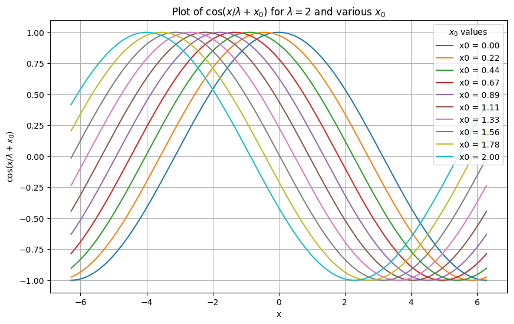
Figure 2: Sinusoidal oscillations of differing phase
The parameter xo is a phase manipulating parameter. If xo = c t, it exemplifies propagation over time. If two separate but contemporaneous wave functions pass through the same region of space, the fields of which they are comprised will add to produce the sum of the two oscillating functions. If two such functions possess the same wavelength lambda, they will interfere with each other in ways that depend on their phase. If they are in phase with each other, i.e., Delta xo = 0, the amplitude of the result will simply be the sum of the two amplitudes. However, if they are out of phase, i.e., x = n pi, where n is odd, they will cancel each other out altogether. This interference behavior is illustrated in the next figure.
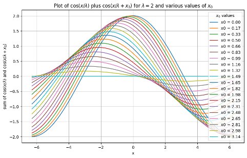
Figure 3: Interference behavior
Clearly, when Dxo is near zero, there will be a nearly complete summation of the wave functions. But, Alternatively, when Dxo is near n p, the wavefunction nearly vanish. That’s enough of the basics for now.
Let’s consider how a reflection telescope works. Consider the reflection surface as a function of distance, f(x) in the direction of an object being observed. Light from planar wavefronts strikes the inner surface and is reflected to a focal point where observation takes place as shown in the figure below:
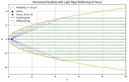
Figure 4: Light from a planar wavefront strike parabolic reflection surface
In order for coherent light to converge at the focus point, the curved surface must satisfy the constraint that the distance every ray of light travels to the focal point must be the same:
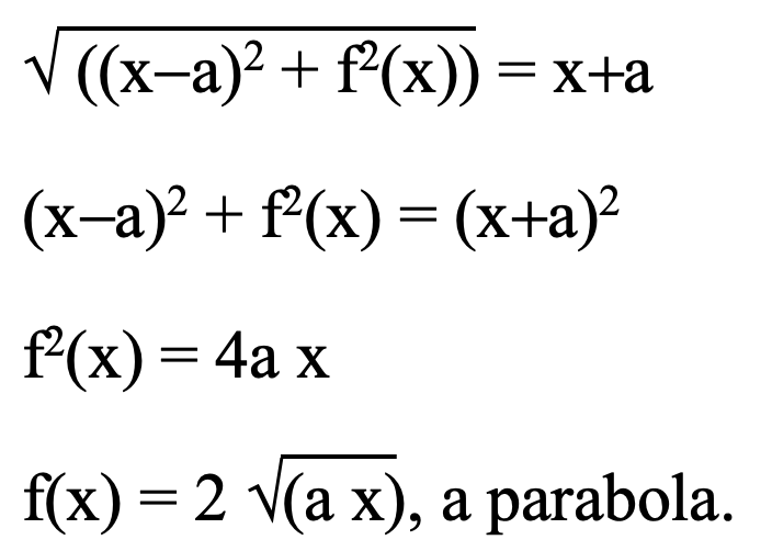
Increasing the size (width, a) of the parabolic dish increases the number of rays of light focused onto the observation point, amplifying the intensity of radiation received.
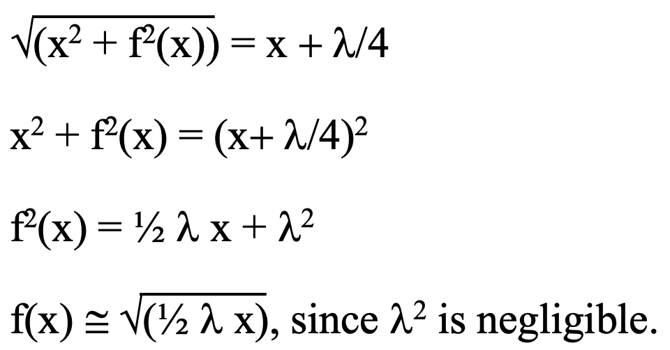
Quite aside from instrumentation, the way light is observed through a medium such as the air at sea level similarly involves a parabolic envelope of ‘rays’ of light from a broad area of each succeeding wavefront as an extension of Huygen’s wavelet theory. It was Gustav Kirchoff who rigorously refined Huygens’ earlier wavelet propagation theory and contributed substantially to spectroscopy. Electrons all along the general direction of a photon’s path contribute to Huygens’ ‘wavelet’ process, replacing the photon at intervals. Constraints on coherent reinforcement define the domains throughout which the scattering by included electrons contributes to a single step of the process. This parabolic coherency domain defined by Fresnel zones is the same shape as a domain originating at a point source shown above. This is a region where plane waves can be assumed rather than the spherical wavefronts. Outside of this central Fresnel zone, reinforcement alternates between destructive and constructive (light and dark circles shown in the center of figure 1) so that the net effect from outside the central region is minimal. A line to/from any point in the central Fresnel zone (or coherency domain) is no more than a quarter wavelength greater in length than along the centerline to the point Po as shown in the diagram of figure 5, below.
This is illustrated below as related to forward scattering by which we are enabled to see whatever we see.
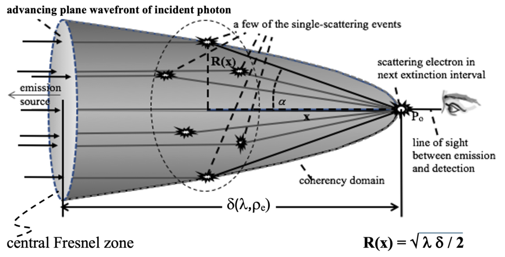
Figure 5: Parabolic coherency domain in a scattering medium
If there were no intervening scattering electrons, a constant phase wavefront emerging from the emitter would spread as a spherical surface as shown at left in the initial diagram of figure 1, becoming increasingly a planar surface facing the ultimate observer. On these surfaces there will be a central circular area – shown at center. This is the central Fresnel zone, throughout which all wavefunctions will be within one quarter wavelength of the same phase. The size of this area will increase with distance from the radiation source.
Although reflecting telescopes also involve parabolic shapes as shown in figure 4, the light rays within these surfaces need not be coherent one to the other. They merely add to the photon count from each region. Therefore, there is no size constraint on the parabolic shape. A coherency domain on the other hand, although also parabolic, is exclusively conceptual in nature. What occurs as an incident wavefront proceeds through this domain is that it encounters electrons that are free to oscillate in resonance with the wave function. This resonant acceleration of electronic charge produces secondary radiation from each electron. This secondary radiation will be completely out of phase relative to the incident wave and will therefore tend to cancel it. When there is a sufficient number of electrons, not only will the original wave function be nullified, it will be replaced by a virtually identical, but oppositely phased wave function. This process is a continuous process, with each electron occupying the position Po in figure 5. It involves all electrons and their overlapping coherency domains along the path of incident radiation.
The coherency domain is defined solely by angles and distance to assure that all incident and secondary radiation are coherent according to criteria illustrated in figure 3. The length of this coherency domain, delta, which determination is made elsewhere on this site, is inversely proportional to electron density and wavelength. This cloning distance is (coincidently) how far light must travel in a medium before the speed of light is altered by the different density of scattering electrons in the new medium rather from that of the medium it just left. This distance, d has been determined to be:

Here me is the mass of an electron, c the speed of light in a vacuum, rhoe is the electron density, and l is the wavelength of the radiation. This distance is a few millimeters here on earth but thousands of light years in intergalactic space.
The number of electrons involved in a single photon cloning process is on the order of :

For visible light in the intergalactic medium, this is on the order of 1035 electrons, but on the order of 1010 at sea level on earth.
Leave a Reply